|
This is the
heater case assembly as it came out of the car. I got very
lucky
and bought this on ebay at a very reasonable price. As you
can see, the
paint isn't too bad but that round gasket/seal on the top has to
go bye-bye!
.jpg)
This case
has been not apart before. Note the (8) small screws around
the
outer edges of the case. These are the factory screws from what
I've been told.
.jpg)
Here's a view from the side.
this little honey is in pretty good shape
.jpg)
This is
actually the bottom or the vent side at your feet in behind the
radio and center console. Dusty, but that's about all.
.jpg)
Last but
not least, the final side view before disassembly.
.jpg)
First I
thought I'd take out the three bolts holding in the fan motor
and remove the top of the case. Wrong!! That is tack
welded together.
The (8) outer screw or rivets in most cases have to come out to
get inside.
.jpg)
OK, the tops off and now the internals are coming out.
.jpg)
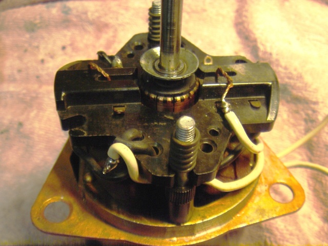
Note the
motor and the proper way to wire it to make sure you're
blowing air across the heater core and into the car, not sucking
it out.
The black wire goes to positive and the green and yellow go to
negative in this case. I will be checking that before this
is put on
the shelf for reinstallation should the need arise.
.jpg)
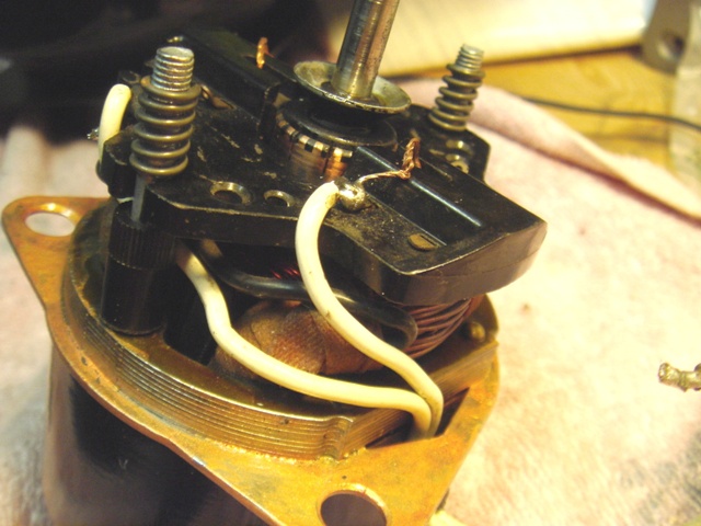
Here's another view of the
infamous and no longer available resistor.
The next move will be having this motor disassembled and the
internals
tested and rebuilt at Yankee Auto Electric here in Pawtucket.
It looks
very good and runs quietly, but I want to be sure before it goes
back in.
.jpg)
Here is the annoying fan
blade and shaft clip, which I will leave alone for now.
Now for two of the pictures
from Jim to show the inside of the motor.
.jpg)
Here's a
look at the heater core all ready to come out. No, you do
not
bend the brackets and force it out of the top.
.jpg)
Remember
these last (5) screws ? This side also supports
the
shaft for the lower air door which keeps your feet warm when you
open
the vent properly.
.jpg)
OK, that
was easy enough and out it comes.
.jpg)
Now to add a few more from
Jim on how to easily and properly remove the shaft assembly from
the box.
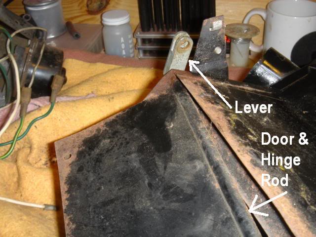
This puzzled me as to how to
remove it, but mine was fine so I didn't need to. Jim will
show us the way.
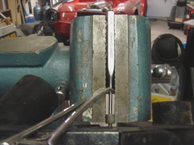
You will need to clamp the
LEVER into a vise and then drive the shaft down and out of the
lever with the punch.
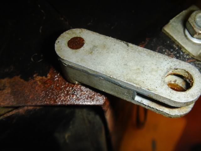
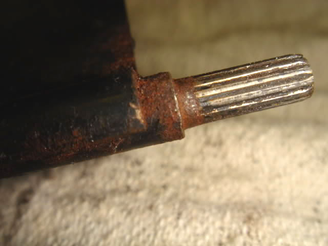
These are the splines on the
end of the shaft that fit into the lever.
After cleaning them up, a little Anti-Seize wouldn't hurt when it goes
back together.
Not that anyone is planning
to ever do this job again in their lifetime.
Thanks again DIGITAL J1M!!!
There you
have it. One disassembled TR6 heater case assembly.
I got
very lucky. This thing is nearly perfect. Someone
rebuilt this not long ago.
.jpg)
These next few shots are for
dimensional questions that you may have.
Overall dimensions of the heater core are 10" X 2.625" X 4.5"
.jpg)
It doesn't look like it, but
the ruler is at the edge of the core end cap.
.jpg)
That end
cap measures exactly 2.625" wide .
The actual core itself is 2" X 4" X 8".
.jpg)
That's a total of 4.5" across
and the tubes are 3.25" center to center.
.jpg)
Here is the parts
kit RFK 1671 that I ordered from TRF with
the installation bolts, washers and insulated bushings for the
mounting tabs on each corner. Also the foam seal, SLP 177,
is now a strip, made to wrap around the top of the housing.
It is included in the kit.
.jpg)
This dark
spot across the core had me concerned since it was green.
As it turns out, it was really nothing but a stain.
.jpg)
First phase
of core testing is to install fittings to pressurize the core.
Then we pump it full of water under controlled pressure or you
could
blow that covers off or split the core. Neither option is
good at this time.
It seems that these cores are starting to become very hard to
get, even
for the radiator repair shops. Daniel's is trying to find
a source for me.
.jpg)
Nice day to
take your core for a swim! 18lbs. PSI water pressure for
five minutes under water and no bubbles. Plus a complete
visual
inspection of the cover tanks show no problems ahead.
Heater core testing courtesy of Daniel's Auto Repair, Pawtucket,
RI.
.jpg)
The motor was disassembled, tested and cleaned internally
at
Yankee Auto Electric in Pawtucket. No problems inside,
although when
Brad finished lubricating the bearings, it spins a lot more
freely than
before, which is much better than my new motor that I put last
fall.
.jpg)
The commutatrr surface was
cleaned and the resistor was checked.
The brushes in the motor were hardly worn, so they stayed in
place.
Sadly my eBay "like new" switch is no good, but better to find
out now.
.jpg)
This is an accumulation of
what you will need to put it back together.
The (13) case screws are #6 X 1/4" and the (3) bolts to the motor are TBD.
The foam tape is used to seal the top of the case together to
keep air
from blowing back out when the lower door is closed and you want
the
hot air to go to your defrosters and not the inside of the dash.
.jpg)
This is a look down inside
the case with the heater vent door in the closed
position. The foam should seal tightly against the frame
of the case to keep
air inside and going up to the defrosters. This foam for
the lower door
is 1/2" thick by 3" wide by 9 1/2" long.
.jpg)
Here's another view of the
foam on the lower door and what the dumb
previous owner of the car that this came out of did to the case.
I had to
straighten the case in several spots to get the door to line up
and open
and close smoothly. While I still have work to do to clean
up the pry bar
marks on the case before I paint it, I want make sure that
everything
works smoothly before I paint and reinstall it.
.jpg)
The case has been completely
cleaned and sanded down and painted.
Now to reassemble in reverse order.
.jpg)
This is a good time to check
the arrows on the fan blade and compare
them to the direction of the wiring for the motor to insure
you're in sync.
.jpg)
The little metal sleeves push
out of the new bushings with the help
of a pencil or case of a ball point pen. Take these out
before you try
to fit the bushings into the three (3) mounting holes.
.jpg)
After fitting the rubber
bushings into place, just slide the sleeves into
position and the top is ready to mount the fan assembly.
.jpg)
With the panel upside down,
this is the position of the fan assembly
which will allow the wiring to be fit through the bottom of the
heater case
easily. Now's the time to install the double face foam
tape around the
entire bottom of the motor panel to keep the case sealed.
And don't forget
to take the second side off before you mount the panel as I did.
.jpg)
The core goes back in as
before and the side panel needs to be aligned
with the flapper door shaft on the bottom. That directs
the heat to the
floor. It's the smallest hole in the side panel below the
lower core outlet.
.jpg)
Before completely installing
the fan assembly panel to the top, and pull
the wires through the hole, one by one and then fit the grommet
into the case while you can easily get your hands in to work.
.jpg)
Now's the time to make sure
that the tape is of of the second side of the
foam. Last step is to install the #6 X 3/8" screws across
the tops and
sides and it's ready to go. I decided not to install the
foam around the
top until this case needs to be installed. Which I hope,
is never!!!
On to the next project, gauge
rebuilding 101. |