|
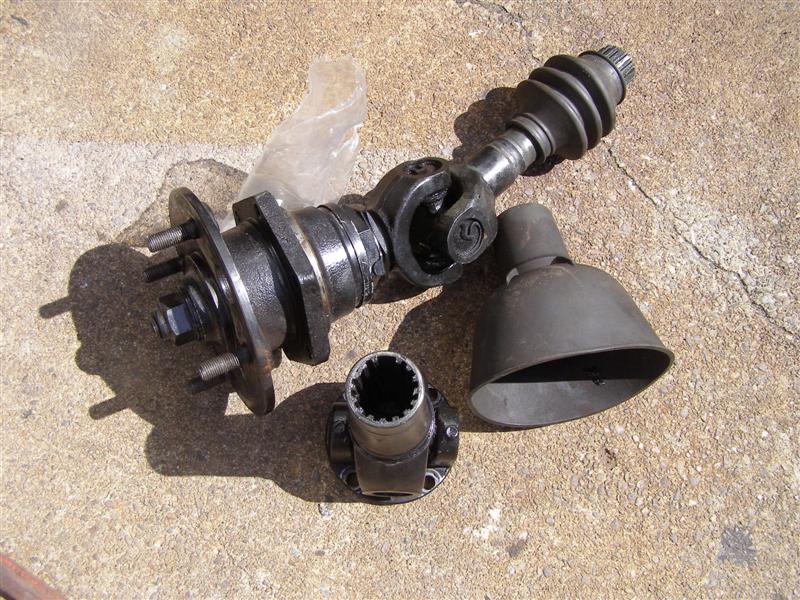
These are the new CV Joint Axles from Richard Good of Goodparts,
Inc..
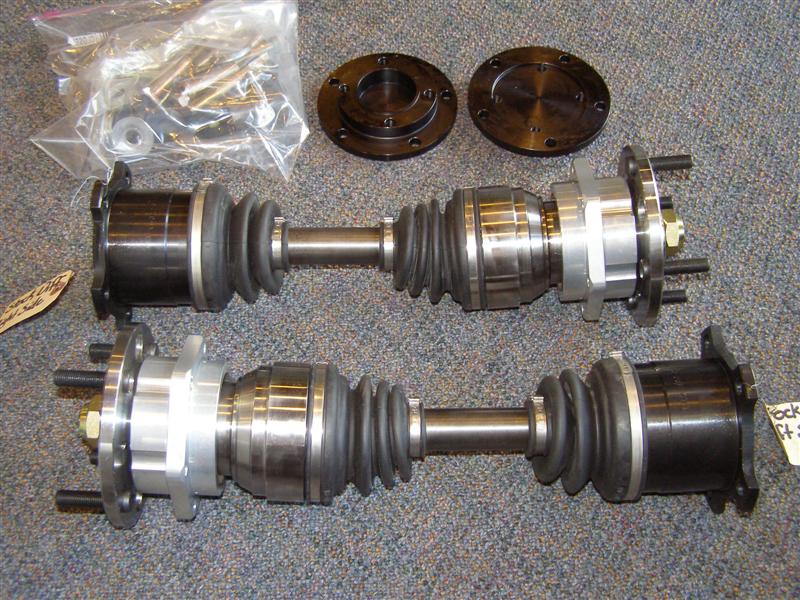
Modern
technology and great machining.
These are
top quality parts and will eliminate any future issues.
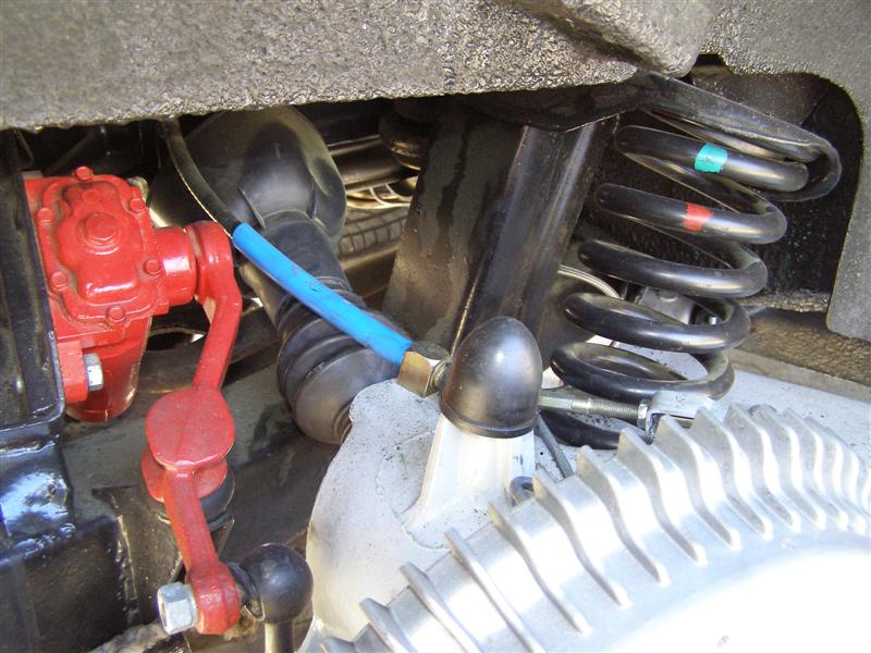
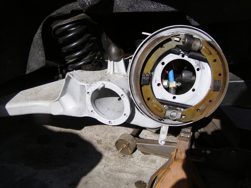
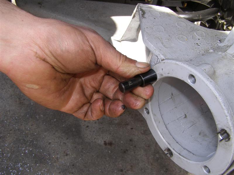
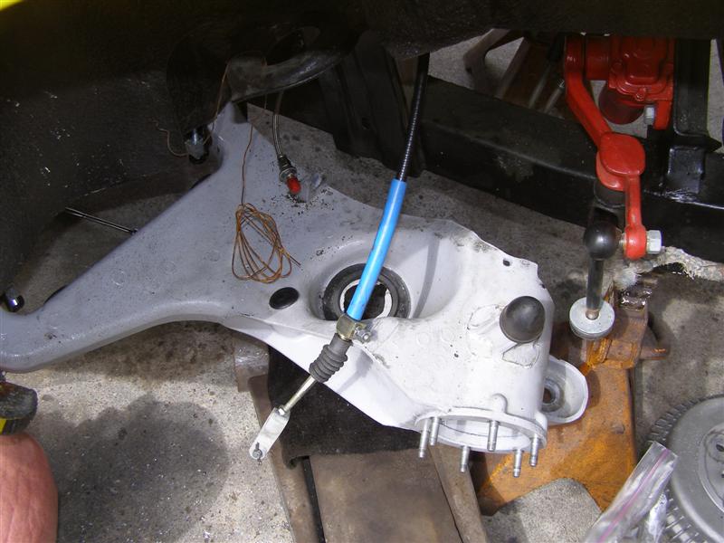
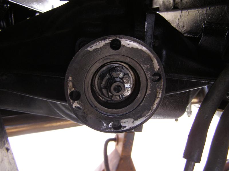
Off comes the rear wheel, the
two screws holding on the drum and then you can get at the nuts
through the hole in the axle.
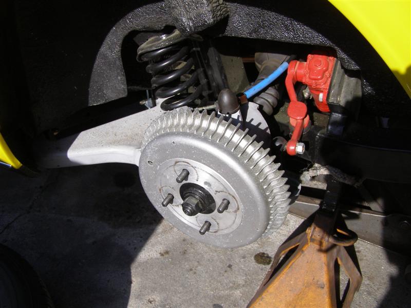
That little guy in there with
the black boot on will be coming out soon.
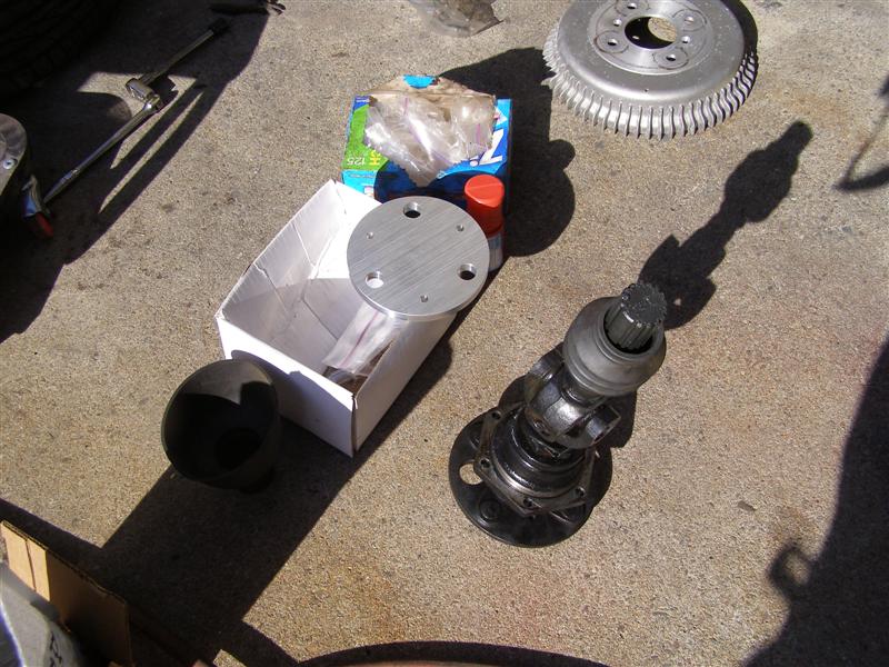
After the six nuts are
removed, the axle assembly should slide right out. The
Patton Repair Kit is on the left waiting to get started.
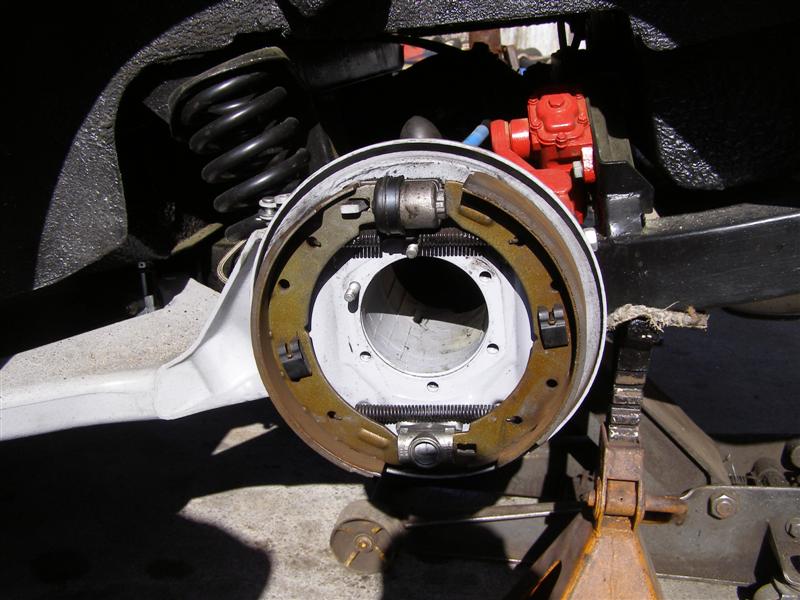
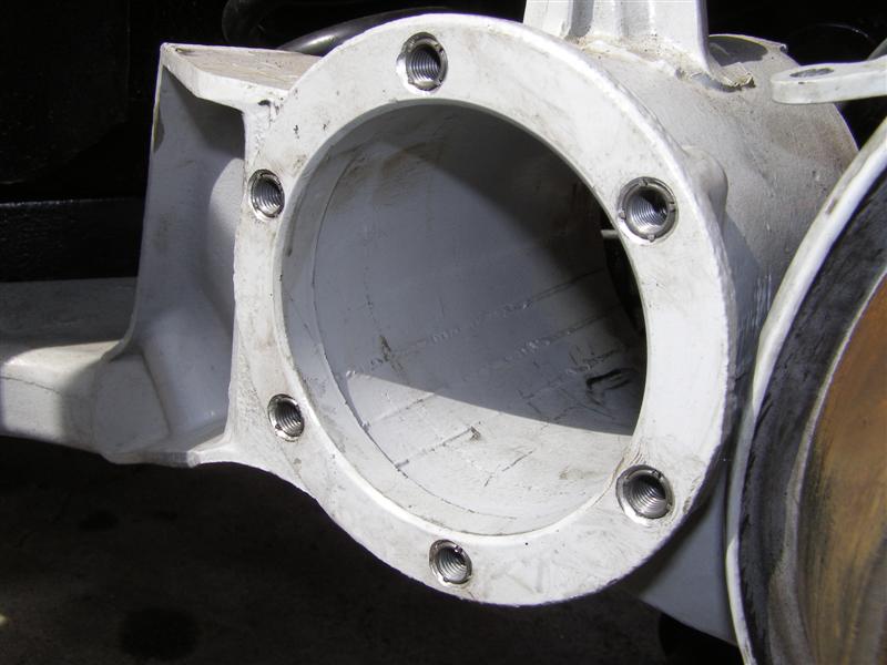
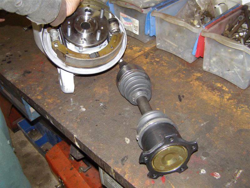
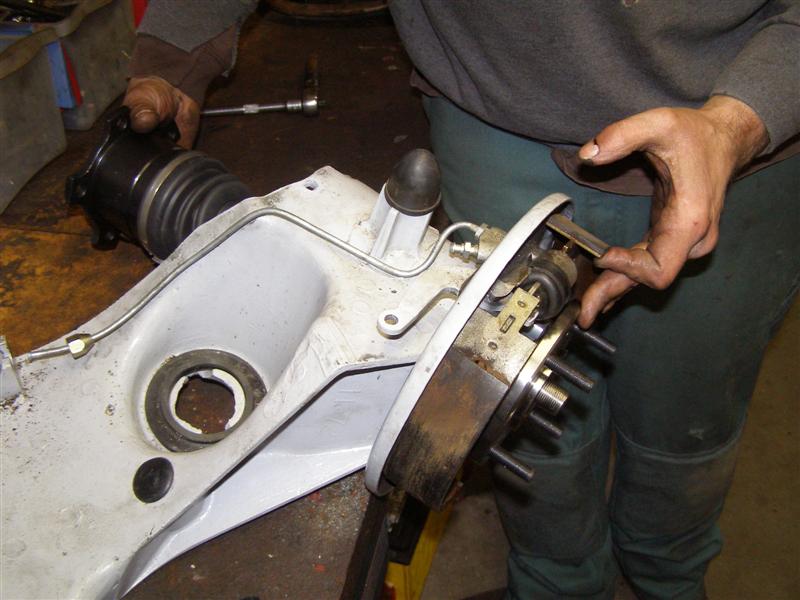
Drum's off, axles out and the
nuts are removed, albeit along with some studs, so we can lift
the backing plate away.
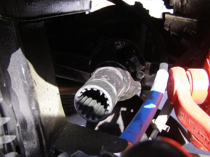
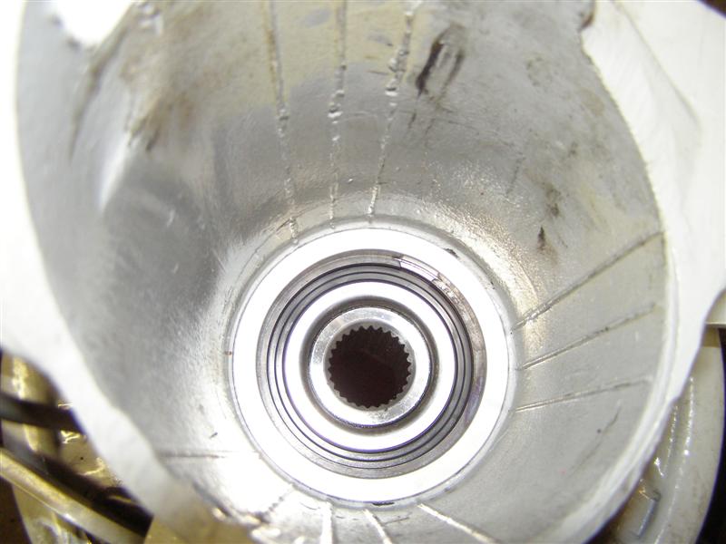
This is the inner shaft that
is bolted to the differential hub flange and will come out soon.
You can get these from this angle
OK, that's done and safely
out of harm's way for now.
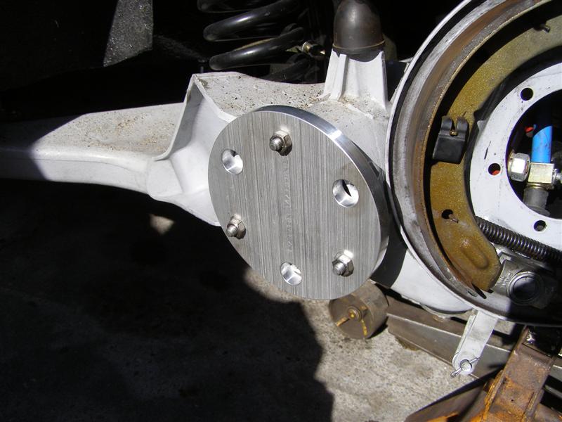
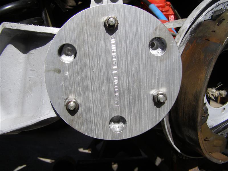
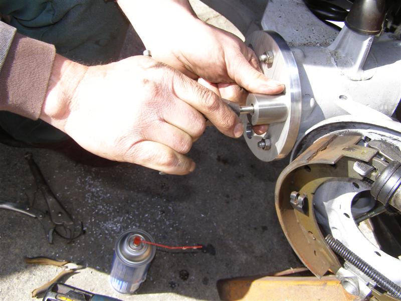
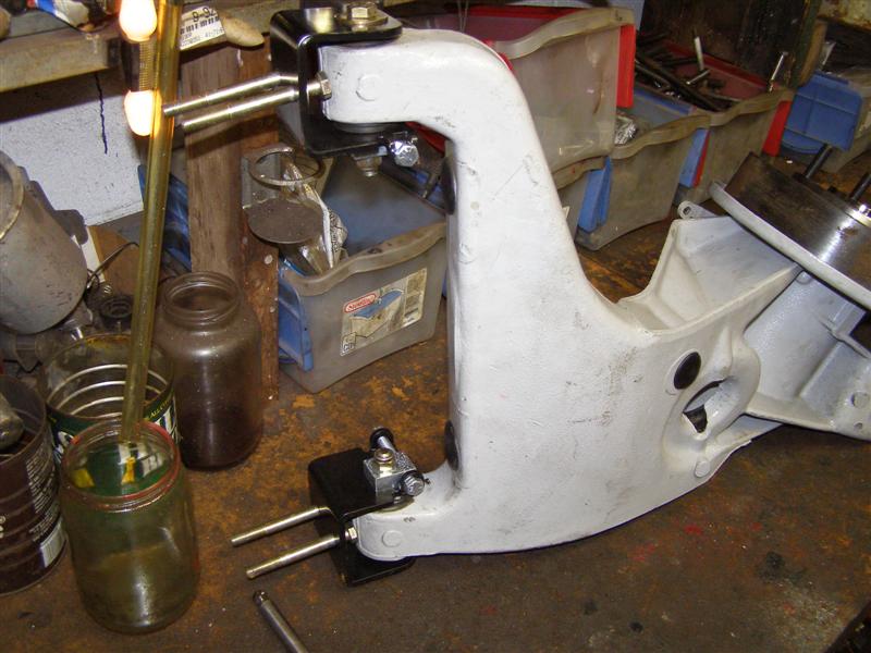
Three (3) studs go back in
exactly as shown and the nuts hold the guide plate in position.
These are machine fit parts
and are very tightly toleranced to fit as they should for
perfectly straight drilling.
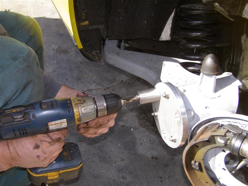
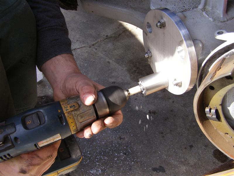
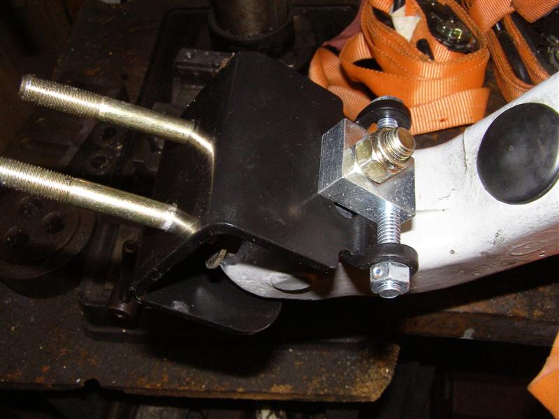
The guide plate and
drill mandrel is in place and ready to set the new cobalt bit on
it's path.
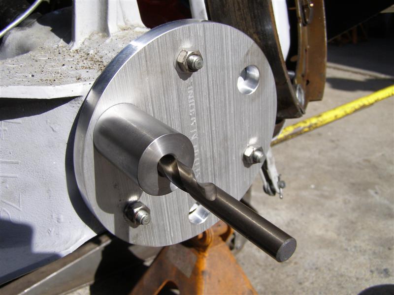
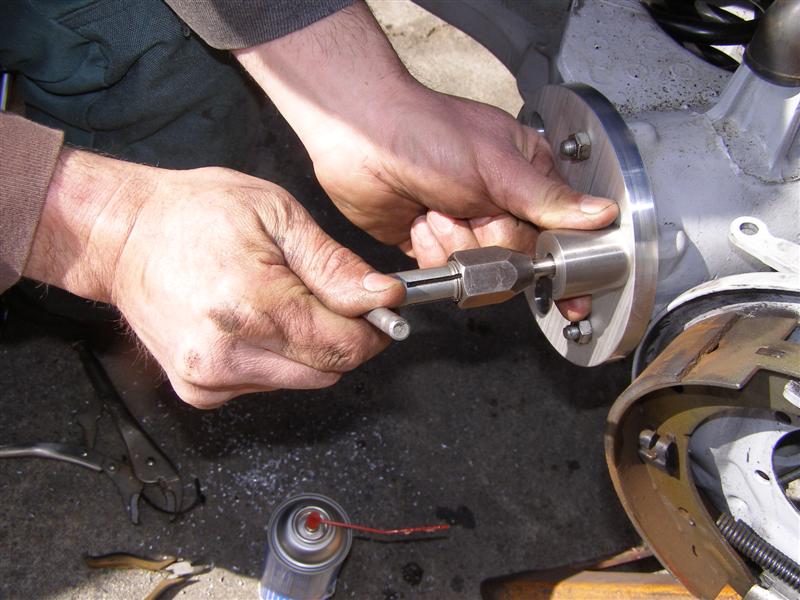
A view from head on so you
can see how this is set up for the drilling. The first
three will be drilled, tapped and
have the Key Lock Inserts installed and then the guide plate
will be refit to the newly installed studs and the process
begins again.
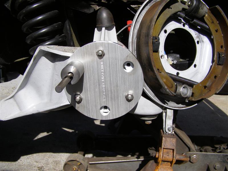
There is a specific depth
measurement determined by measuring the hole depth and
transferring it to the drill.
A good illustration is shown
here, ala
Rick Patton & BobbyD.
The Key Lock (KeenSert) procedure is clearly
outlined here in the Key Lock instruction package.
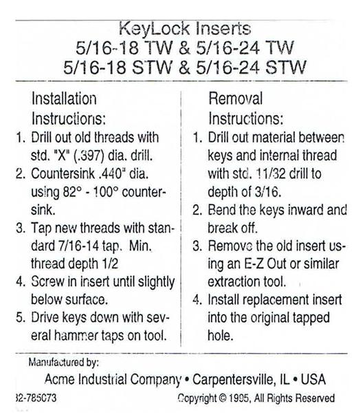
And use a
good aluminum cutting oil for drilling and tapping.
There is a hard to see black
line on the bit that was soon replaced with tape to insure we
didn't go to far.
These mandrels are made form
D2 tool steel and will last a long time. You must get the
exact size bit (X-.397" diameter)
specified to make this work
with the 5/16"-18 to 5/16"-24 Key Lock Inserts available from
McMasterCarr.
No "close enough is good
enough" on this project.
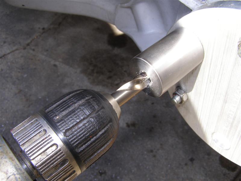
There's the tape and I would
highly suggest wearing gloves as aluminum chips cut quickly and
deeply into your skin if unprotected.
And anyone not wearing safety
glasses when starting this job should not ever be allowed to
have a wrench in their hands again.
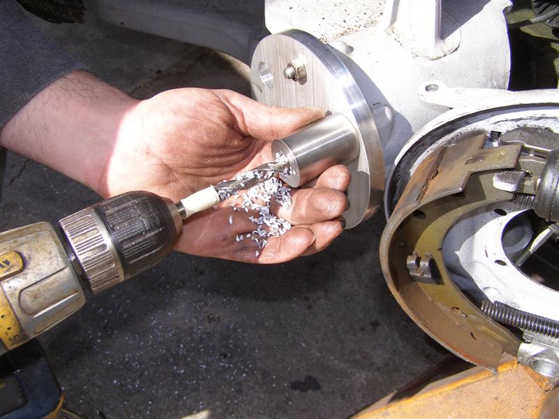
Drill slow and steady,
removing the bit several times to get the chips out of the bit
and guide.
There are the first three
drilled out holes waiting to be cleaned out and have a .400"
chamfer using a 82-100 degree C/S bit on the entry.
And this is just the guy to
do it. Again, slow and careful and use cutting oil here
too.
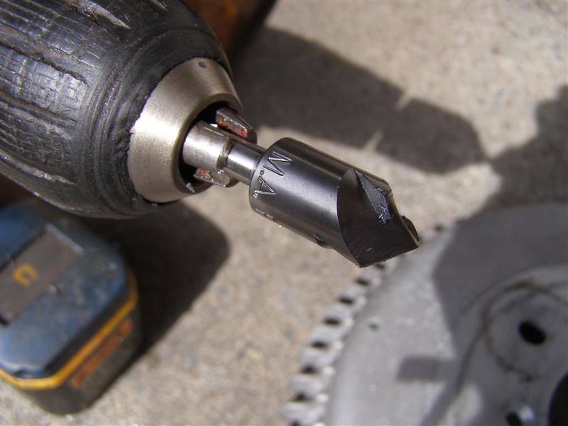
Aluminum is soft, so go slow
and take your time with the countersink. It is needed for
the inserts to lock in.
Thread tapping time and this
again is done with a precision machined mandrel to act as a
guide and insure perfect work.
Cutting oil shown above and
the tap is done a bit at a time, not all at once. Use oil
and blow out the chips carefully to protect eyes and the car.
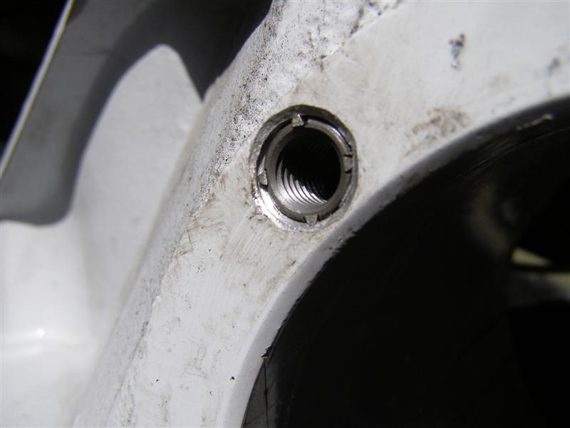
There are the first three
ready to be cleaned and get the Key Lock Inserts installed.
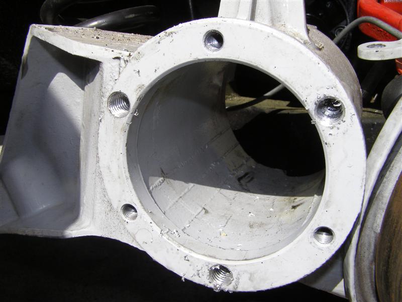
The inserts thread right in
finger tight. If not, STOP, remove it and clean or retap
the threads. NO resistance on these going in.
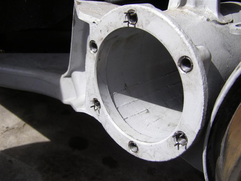
When you read the
instructions, you will see that the four (4) prongs remain
standing proud above the surface after the inserts are
installed.
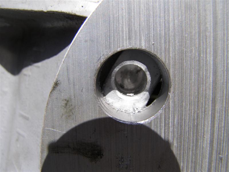
Once in and bottom out, this
tool is used to set the prongs to the proper depth inside the
.045" chamfer.
Just like that. These
can be removed if need be, but will probably never have to come
out.
BobbyD has proven that a Grade 8 Bolt or stud will shear before
these studs pull out, so this repair is for life.
Now you can use these to
secure the guide plate down for the remaining three to be
drilled and tapped.
Repeat the processes above
and you will have the last three ready to be locked in place.
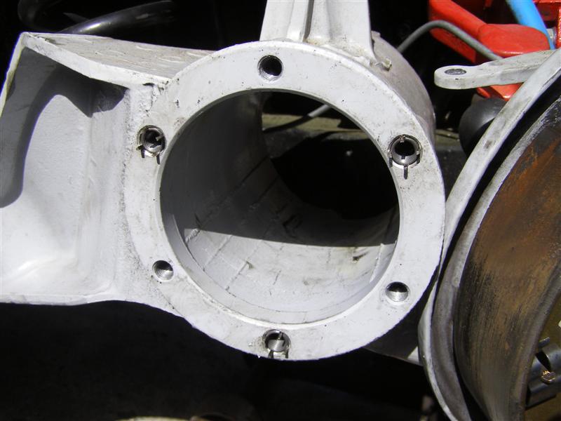
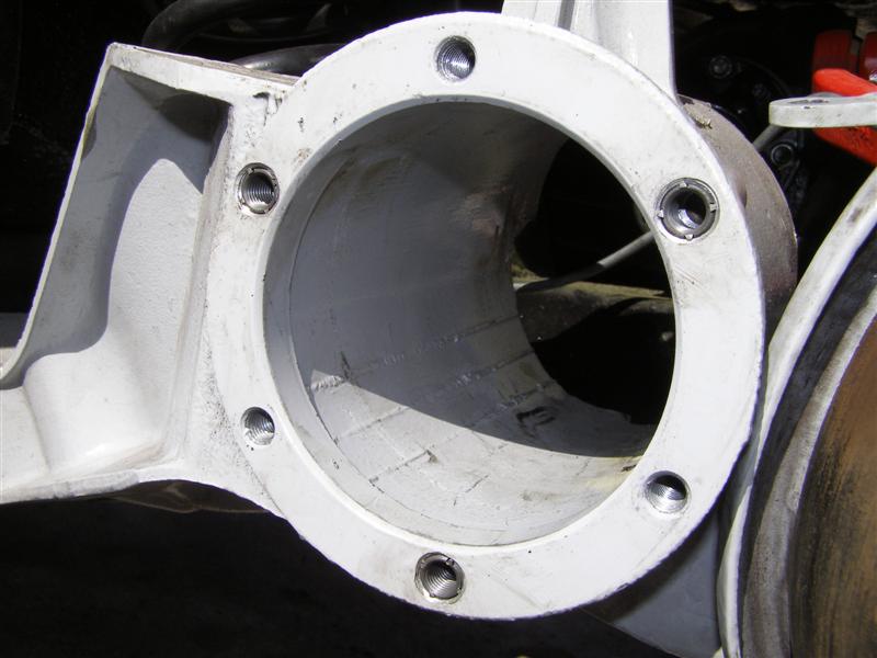
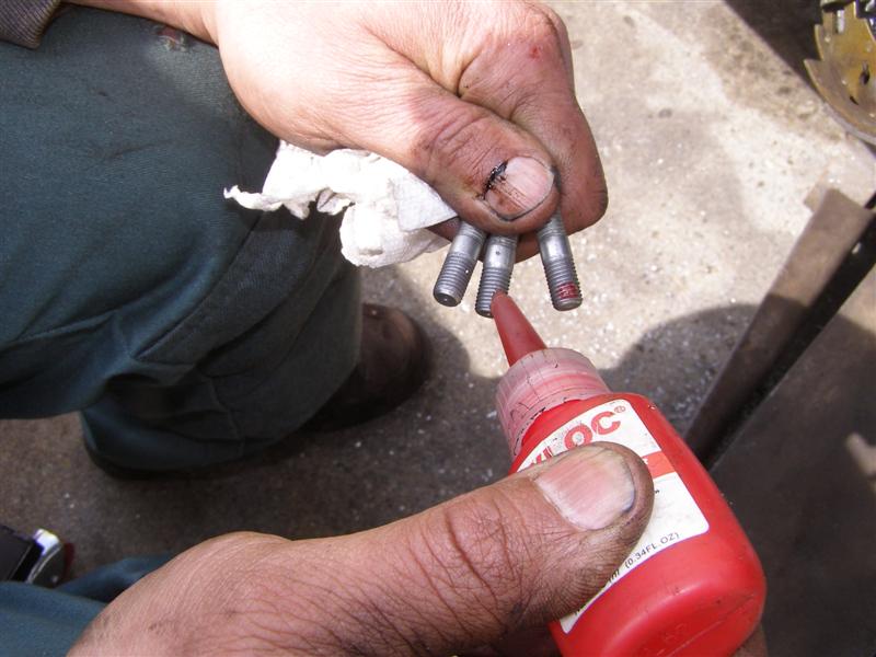
All six are set and ready to
install the new studs.
A little LocTite Red never
hurts either.
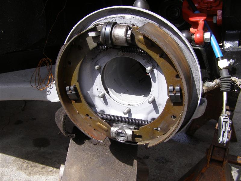
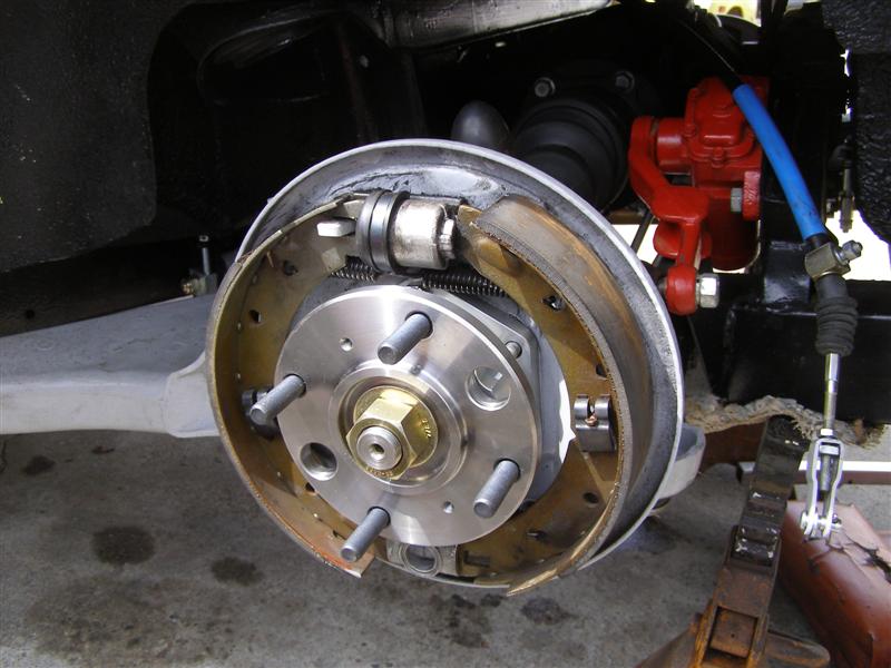
The backing plate is back on
and ready for a test fitting of the axle hubs.
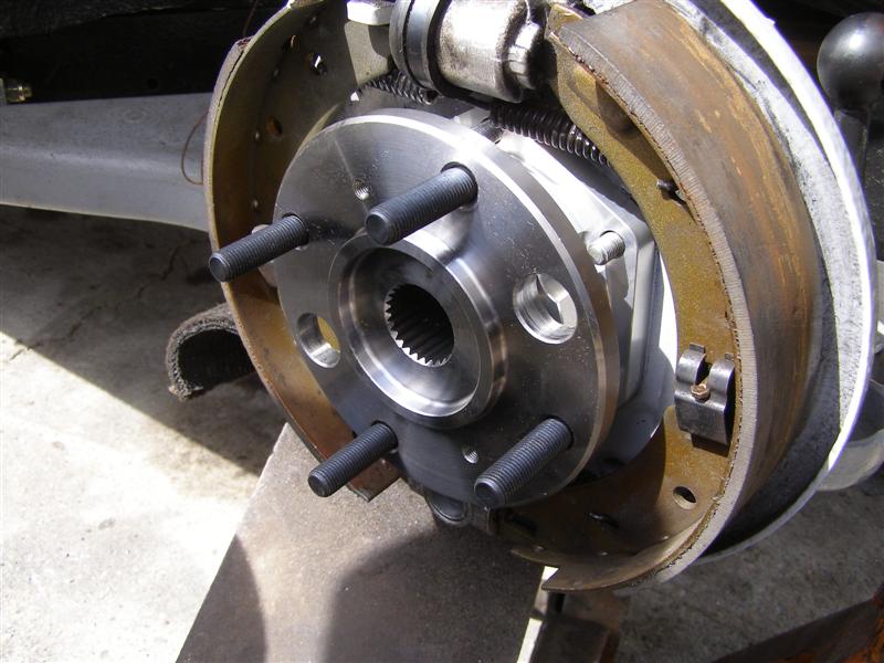
That looks very nice sitting
in there. It fits perfectly on the newly installed studs
and down on the trailing arm.
Off with the hub and backing
plate again and time to remove the trailing arm from the car.
SHIMS will fall out if you
are not careful!!!!
Count them when you drop the
arm down and mark how many went on each side as you remove them.
You will not remember, so do
yourself a favor and write it down.
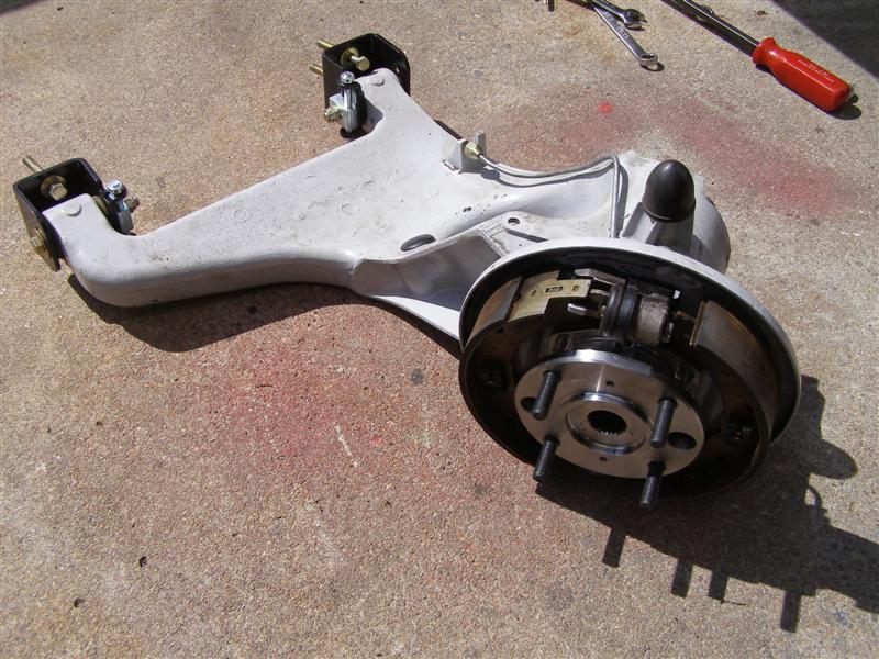
Now a little bench time for
the T/A and axles assembly.
These are the GoodParts
Camber Adjusting kits that I installed last year.
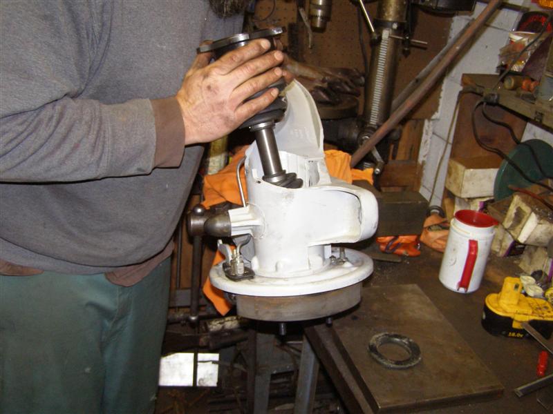
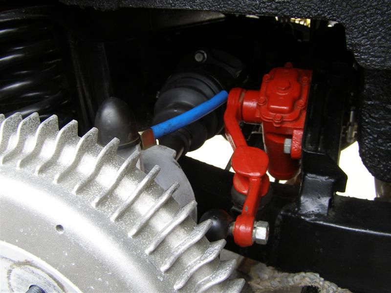
Erik begins test fitting the
axles. We want to be sure that there is no rubbing on any
of the inside surfaces.
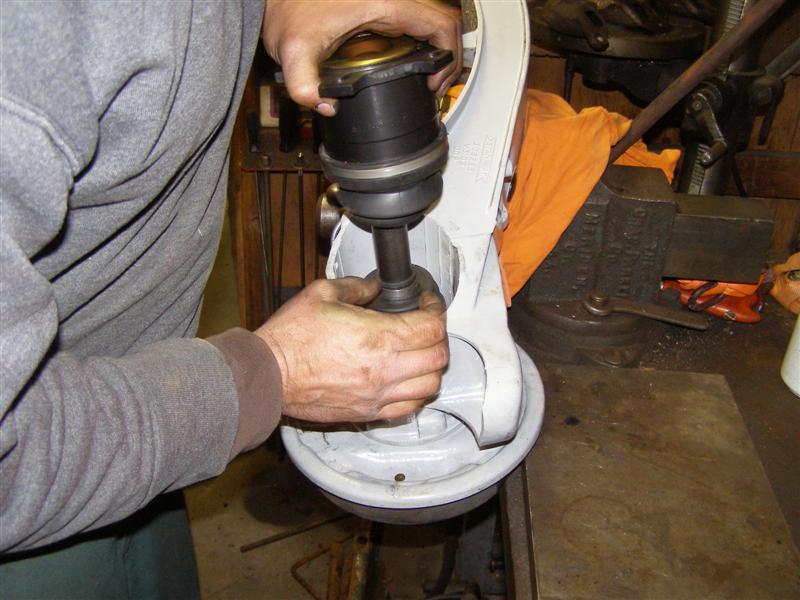
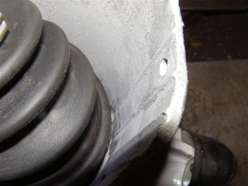
Eric is moving the back of
the axle in a 360 degree motion to insure that clearance is
there for the shaft to turn without hitting the casting.
This area is fine, it's down
below that can be an issue.
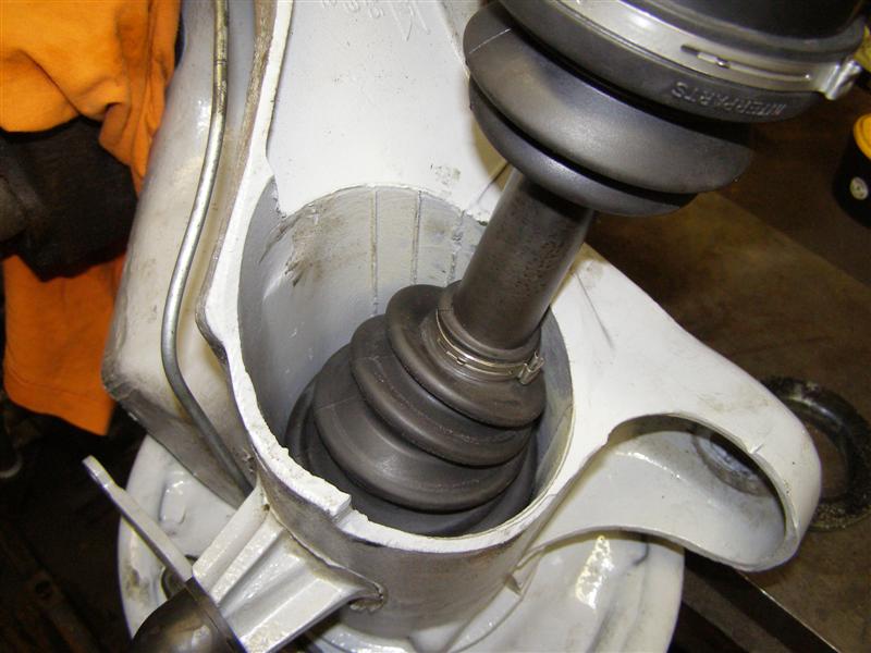
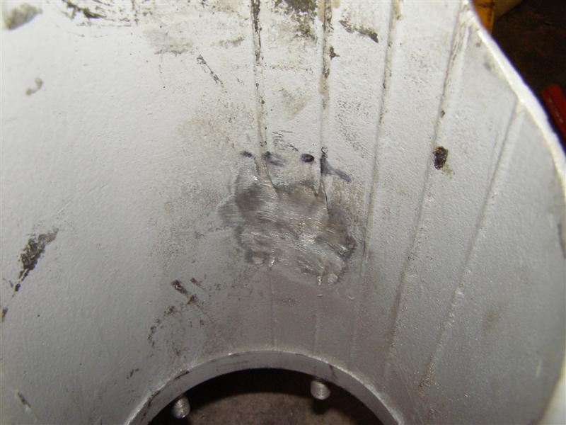
This is the potential problem
area that I mentioned above. While this side was OK, the
right needed a bit of grinding to get it clear.
That side is perfectly clear,
so now it's time to do the adapter installation.
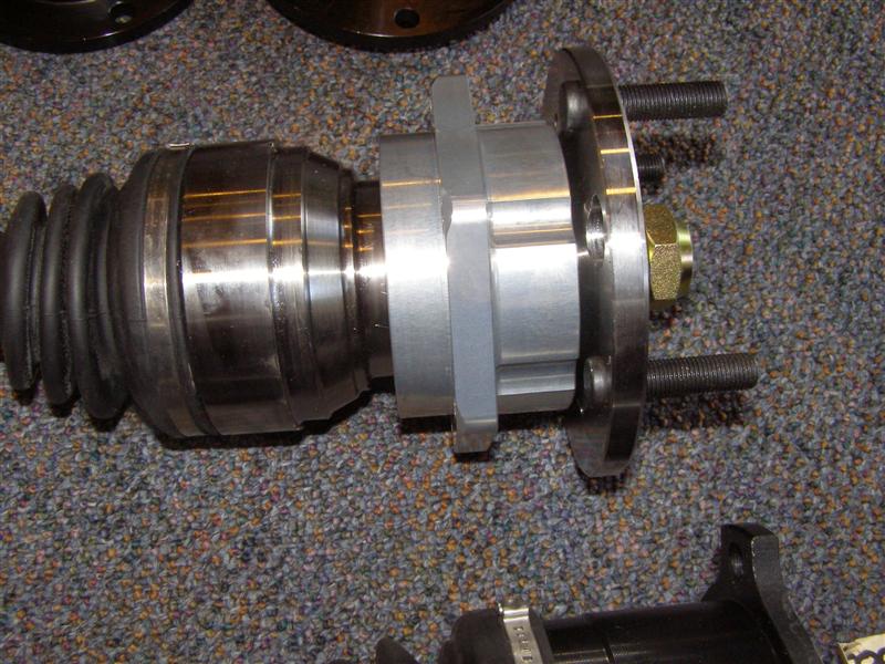
Obviously, the four bolts
come through the back and thread into the adapter. Make
sure all surfaces are clean as these fit tightly.
Before these two parts are
bolted together, a bead of silicone needs to be run around the
ridge on the axle that mates to the flange.
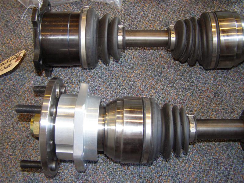
The axle assembly bolts on
from this side there are nuts that go on the back of these that
require torquing.
Just a picture of the entire
old axle before it heads home to a storage bin in my basement.
I carefully held the axle
assembly while it was being torqued and then used some wire to
hold
it in place while we get the trailing arm ready to get set into
place.
At this point the hub is
bolted into the axle and the splines will mesh upon assembly.
We found that this a great
two man job. One to be under the car and guiding the four
(4) bolts into the frame,
as the other supports and helps twist the arm into position,
while making sure the splines line up in the hub and shaft.
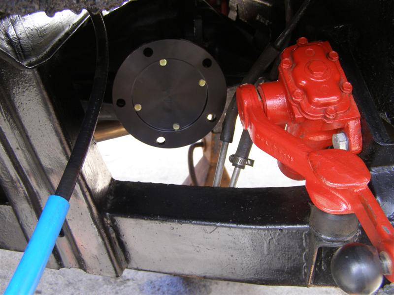
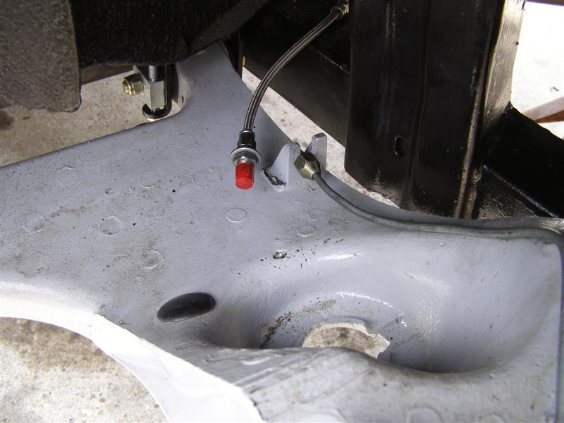
These caps help make sure
brake fluid doesn't run all over as you may bump the line going
back and forth with the arm.
OK, all back in place and
just about ready to go.
Prior to complete assembly,
there is an up and down procedure spelled out in the GoodParts
instructions,
that we still performed, even though we moved the axle within
the arm to maximum extension while on the bench.
Why?
Because Richard says to do so
and to insure that nothing else on the car causes any
interference with the new larger axle assemblies.
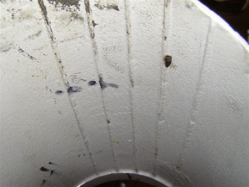
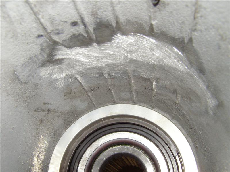
This is the potential problem
area that we talked about earlier. The black mark shows a
set of ribs that
are not near as prominent on the other trailing arm, so a little
grinding is in order here.
BobbyD used a neat flapper
for his and we used a smaller version, as there was very little
that needed to be removed.
Before
A small amount removed.
Testing 1, 2, 3........
A little more out and all
clear for assembly. Repeat the process as before and you
will see what's shown next.
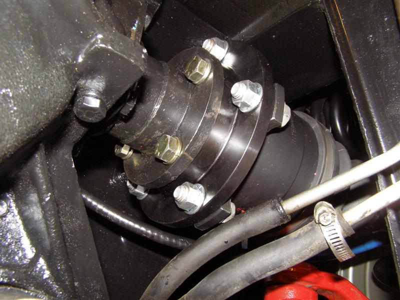
This shows the inside view
from down under of the adapter to the hub and the flange to the
adapter bolts and nuts
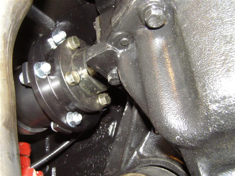
Good time to check all of
these and make sure they are tight and in good shape.
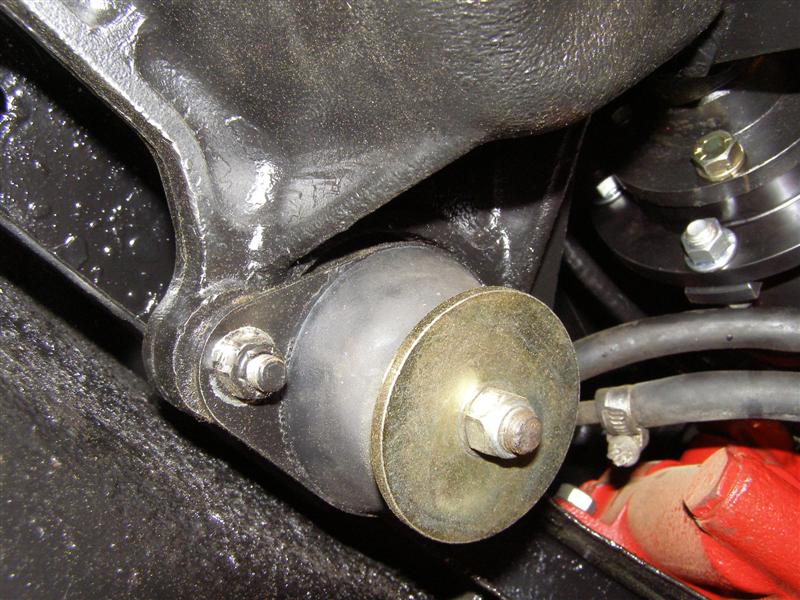
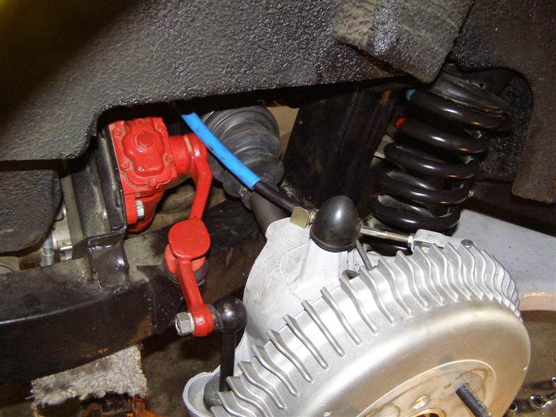
And the other
side......plenty of clearance on fuel and vapor lines.
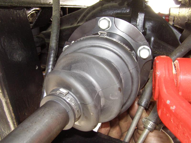
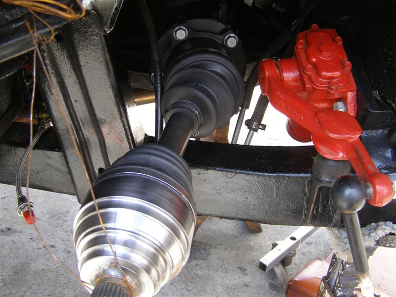
Back together and ready for
wheels and tires. Yes, I did clean everything before the
wheels went back on.
Thanks again to Eric for
another great job!
40 Industrial Road
Cranston RI 02920
(401) 352-0888
hermajestysauto@gmail.com
|